


On this page you can download various software. The PC software +divide Manager and the Simple MIDI Monitor for the ZX Spectrum Next were written by me. Other software packages were compiled by me, but come from other developers.
 Table of contents
| +divide Manager | PC software to manage virtual Plus-D images |
| DivIDE Plus Manual | DivIDE Plus interface manual in PDF format |
| ResiDOS v2.30 | ResiDOS v2.30 - Installation package for DivIDE Plus and short installation description |
| ESXDOS 0.8.9 | ESXDOS 0.8.9 - Installation package for DivIDE Plus and detailed installation instructions |
| Simple MIDI Monitor | Simple MIDI monitor for the ZX Spectrum Next and the Next MIDI Box |
| ZX MIDI Player | Standard MIDI file player for the ZX Spectrum 128 and ZX Spectrum Next |
| +divide Manager v1.00d | Aktuelle deutsche Version v1.00 des +divide Managers vom 08.12.2009 |
| +divide Manager v1.00e | Current English version v1.00 of the +divide Manager from 08/12/2009 |
This program allows you to easily exchange data between a ZX Spectrum equipped with a DivIDE interface and the +divide operating system and a PC. A CompactFlash card or a hard disk can be used as the data medium, although CF cards have proved to be the most reliable.

 General information
Like the Plus-D interface, the +divide operating system uses floppy disks, but these are stored virtually on an IDE disk. To make it as easy as possible to access these virtual floppies, they are arranged one after the other on the disk, starting from sector 0.
However, this poses a major problem if you want to access the data medium with a PC: as there is no file system, the contents are not so easy to read. Although it would be possible to read the data sector by sector on a PC using „hacker tools“, the handling is very cumbersome. Also, direct access is not without risk if you accidentally have the wrong medium in the drive. So what to do?
I have given it some thought, and have come up with a workable solution for accessing the stored data from both the Spectrum and a PC - as long as a few basic conditions are met. And this is how it works:
- A large file is written to the data medium, which fills the entire space used by +divide. This ensures that the +divide Manager can access the entire area, and the large file prevents other PC programs from writing to this area and destroying the contents.
- The first image (GO TO *1,0,0) must NEVER be used on the Spectrum. This area contains the FAT structure of the data medium, which must be preserved.
- Due to the FAT structure mentioned above, the image file does not start at sector 0, but after the FAT area, although this position varies depending on the data medium used. A procedure is required to determine the exact position of the first usable virtual disk (image 1), but this only needs to be done once.
- From now on, the image file on the data medium should only be edited using the +divide Manager on the PC. It is important that the clusters of the image file are arranged in sequence, otherwise the data will not be at the expected position. If the file is edited with other software, the file may be fragmented and the image positions will not be correct.
I would like to mention one disadvantage: When you set up a data medium, all data is lost. So you have to set up the data medium in the Spectrum before using it for the first time. In any case, I know of no way to create a FAT structure and a image file at a later date without losing data.
Installing the software
The installation only consists of creating a directory. The dmanager.exe file is simply copied to this directory. It can then be run directly. After the first start, the +divide Manager will create a file dmanager.ini in the same directory, where the drive letter of the last used medium is stored. No other files are created by the +divide Manager without user intervention, and no entries are written to the registry.
The ZX Spectrum and the DivIDE interface must also be prepared by installing the +divide firmware. If you use the widely used FATware or ESXDOS instead of the +divide firmware, the installation is very easy: unzip the file divide-firmware.zip and copy the file +divide.tap to a normal data medium (preferably a CF card). Select this file on the Spectrum using the disk browser and start it with LOAD "" (don't forget the jumper). Users of a DivIDE Plus have it a bit easier. Here the +divide firmware is already installed and only needs to be activated with OUT 23,4 after power up or reset.
For those in a hurry: Quick guide to setting up a medium
The following is a short description of how to set up a data medium for use with +divide. However, I recommend that you read the full description.
- Format the data medium (CF card or hard disk) using the FAT file system (not FAT32).
- Start the +divide Manager and select the drive letter of the data medium in the top right corner.
- Click on Create medium, confirm the security prompt, enter the number of disk images you want (or confirm the default) and sit back - depending on the size of the data medium and the number of disk images, this may take several minutes. A status window at the top right will keep you informed of the progress. When the process is complete, an information window will appear with the next steps on the Spectrum.
- Now insert the data medium into the DivIDE and switch on the Spectrum.
- Enter GO TO *1,0,1 on the Spectrum, then CAT 1. The catalogue of a blank disk should appear. Now type SAVE d1"test".
- Turn off the Spectrum and insert the data medium back into the PC.
- Click on Position medium and a list will appear in the left-hand window, with the name "Test" in the first image - done.
Detailed description of all features
Left display window
An overview of all disk images is displayed here. Each entry consists of the image number and the first filename found. If the disk image is from a SAM Coupé, the disk name is displayed instead of the first filename. If the catalogue of a disk image is empty, <empty> is displayed. You can select a disk image with the mouse and its entire contents will appear in the centre display window.
Centre display window
After selecting a disk image, the complete contents of that image are listed here. The following data will be displayed:
- CAT record number
- Filename
- Filetype
- Further details depending on the filetype:
- Basic program: length (,start line)
- Number array: length, variable name
- String array: length, variable name$
- Code: start address, length
- Screen$: start address, length
- Opentype: length
SAM Coupé files are displayed, but the file data is missing. This window is for information only. Although individual entries can be selected, no other function is associated with them.
Open medium
This function is used to open a medium and display its contents. The drive on which the medium is located must first be selected in the selection box on the right. A medium can only be opened if it has been fully set up, i.e. created and positioned. The +divide Manager recognises this by the name of the media file, which has the following structure: x-y.img
| x | This is the so-called offset value. If this value is 0, positioning has not yet been performed. After positioning, a 3 or 4 digit number will be displayed here indicating where the first disk image starts in the media file (number of sectors from the start of the file to the first disk image). |
| y | This value contains the number of disk images. |
For media created with an older version of the +divide Manager (< v0.50), the filename has the structure x.img. The number of disk images is missing here and it is always assumed that the entire data medium will be used for +divide. The number of images is then determined by the size of the data medium.
Create medium
This function is used to create a new medium for shared access between the PC and the Spectrum. The data medium must be empty for this function to be performed. It is recommended to format the data medium beforehand. The FAT file system must be used as this is the only way to ensure that the clusters are written in the correct order.
First select the drive containing the new data medium in the right hand selection box. The Create medium function can then be started. After confirming a security prompt, another prompt will appear asking you to enter the number of disk images you wish to create. The +divide Manager will suggest the maximum possible number and if you confirm this, the entire data media will be used for the +divide. If you select a smaller number, there will be free space on the data media which can be filled with other Spectrum files and used with e.g. FATware or ESXDOS. This means that a single data medium can be used for multiple firmwares. After entering the number, a file named 0-y.img will be written to the data medium, where y is the number of disk images just entered. This number will allow the +divide manager to identify the area used for +divide when the data medium is opened. The writing process will take a few minutes, during which time a progress bar will appear in the top right of the status bar.
Important: The medium is not yet ready for use after this operation, it still needs to be positioned. For this reason, an information window will now appear with the next steps to be taken on the Spectrum.
Position medium
This function determines the exact position of the first disk image and thus completes the process of creating a medium. However, a small intermediate step is required: In order for the program to find the correct position, there must be at least one CAT entry in the first disk image on the medium. To do this, remove the disk and connect it to the Spectrum. Then run the following commands:
| GO TO *1,0,1 | Select the first disk image |
| CAT 1 | List catalogue (a blank disk should be displayed) |
| SAVE d1"test" | Saves a program as "test" in disk image 1; the file name and type are irrelevant; the only important thing is that there is at least one entry in the catalogue. |
Now insert the disk back into the PC, select the appropriate drive from the right hand selection box and click on Position medium. If all went well, a list of disk images will appear in the left window, the first of which is the name you entered on the Spectrum. The medium is now set up.
Backup medium
This function allows the entire contents of the medium to be backed up to a PC with a single mouse click. To save time and space, only disk images that contain data - i.e. have at least one catalogue entry - are backed up.
After clicking on Backup medium, a dialogue box will open allowing you to select or enter the directory and file name for the backup. Click Save to start the backup process, whereby the name entered will be expanded by the program. An example:
| Entered name: | Backup |
| Output files: | Backup-0001.dsk Backup-0003.dsk Backup-0004.dsk |
Each file contains one disk image, where the number appended to the file name corresponds to the number of the image. All images are saved in dsk format, the structure of such a file is described below. If you have a lot of data to back up, this process may take some time. The status bar at the top right of the screen will show the progress.
Restore medium
This can be used to rewrite a backup as described in the previous section. All disk images available as a backup will be rewritten to the original position on the medium. All other images will remain unchanged.
After clicking Restore media, a dialogue box will appear. All you need to do is select a file from the backup series (any file), click Open and the restore will begin. Again, the status bar will show you the progress of the operation.
Note: Note: Restore will only work if the data medium already contains a medium and this is also correctly positioned. If this is not the case, the setup procedure must be performed first.
This function allows you to copy a medium where the destination medium can be larger or smaller than the original. If the target data medium is smaller than the original, not all of the images may be recovered (the number of images is greater than the maximum number of images). However, these images can be added manually using the Insert disk image function if there are free places available.
Close medium
This function is self-explanatory. When you are finished editing the medium and want to remove it, click Close medium.
Extract disk image
This function allows you to save a single disk image as a file. This file can then be sent by e-mail or made available as a web download, for example.
First select the disk image you want to extract from the left window, which will display its contents in the middle window. Next, select the file format you want to use from the drop-down box next to the button. You can choose from dsk, mgt and img. See below for a description of each image format. When you click Extract disk image, a dialogue box opens where you can enter or select a file name. You can omit the file extension - the program will add it according to the selected format.
Insert disk image
This allows you to insert an image file into the medium. First click on the location where you want to insert the image in the left window. Once you have clicked on Insert disk image, a dialogue box will appear where you can enter or select the image file. Based on the file extension (dsk, mgt or img), the format is recognised, converted accordingly and inserted into the medium. The previous image will be completely overwritten.
Delete disk image
This function allows you to delete a disk image that is no longer required. Again, the disk image must first be selected in the left-hand window. After clicking on Delete disk image, a confirmation prompt will appear and the image will be erased. All sectors of the image will be overwritten with zero bytes. This is equivalent to the FORMAT d1 command on the Spectrum.
Write a Plus-D disk
Note: This function is only available if SamDisk is installed (see below for more information).
Write a Plus-D disc is very similar to the Extract disk image function, except that instead of creating a file, the selected image is written directly to a Plus-D disk, which must be in drive A:. After confirming the security prompt, a SamDisk window opens, allowing you to watch the writing process. It takes just over 2 minutes to format, write and compare the disk. SamDisk will then close.
Read a Plus-D disk
Note: This function is also only available if SamDisk is installed (see below for more information).
This function already exists in a similar form (Insert disk image), but instead of reading from an image file, it reads directly from a Plus-D disk in drive A:. After confirming the security prompt, SamDisk will also be started for this function and will close when the reading process is complete (takes about 40 seconds).
Exit program
This ends the program :-)
Installing SamDisk
The SamDisk program must be installed in order to use the Write a Plus-D disk and Read a Plus-D disk functions. Although this program was written for SAM Coupé users, it can also be used for Plus-D due to the identical disk format. It was written by Simon Owen and can be downloaded from his homepage. At the time of writing (11/06/2007) v2.0 was the latest version:
http://simonowen.com/sam/samdisk/This program works on the command line and should be copied to a directory in the Windows PATH variable. If this seems too complicated, just copy it to the +divide Manager directory. That's all you need to do. At startup, the +divide Manager checks to see if SamDisk is installed and then activates the two Plus-D functions.
By the way, the +divide Manager uses the following function calls for writing and reading Plus-D discs:
| samdisk /f /v temp.dsk a: | writes the image temp.dsk to disk |
| samdisk a: temp.dsk | reads the image temp.dsk from disk |
Further information
Structure of a data medium / medium
+--------------+--------------+--------------+--------------+~~+--------------+
| Disk image 0 | Disk image 1 | Disk image 2 | Disk image 3 |  | Disk image n |
|              |              |              |              |  |              |
| FAT | (free) |              |              |              |  |              |
+-----+--------+--------------+--------------+--------------+~~+--------------+
^     ^        ^              ^
|     |        |              |
|     |        |              ‘--- Medium + Offset + 1600 sectors
|     |        ‘------------------ Medium + Offset (Offset is in the filename)
|     ‘--------------------------- Medium usable from here
‘--------------------------------- data medium - sector 0
The +divide Manager currently supports 3 formats: dsk, mgt and img. What they all have in common is a size of 1600 sectors, corresponding to 819200 bytes. As these are virtual disks, the data is also arranged in the same way as on a floppy disk: There are 2x 80 tracks with 10 sectors each. The tracks on the bottom side of the disk are numbered 0-79 and the tracks on the upper side are numbered 128-207. The difference between the file formats is in the arrangement of the tracks:
dsk: 0, 128, 1, 129, 2, 130, 3, 131, 4, 132, …, 78, 206, 79, 207
mgt: 0, 128, 1, 129, 2, 130, 3, 131, 4, 132, …, 78, 206, 79, 207
img: 0, 1, 2, 3, 4, …, 77, 78, 79, 128, 129, 130, …, 205, 206, 207
The sectors within a track are arranged in the same order 1-10 for all formats. As you can see, the dsk and mgt formats are identical, but the mgt format seems to offer more (e.g. multi-images), unfortunately I don't have any more information. The dsk format seems to be the most popular, so I used it for the backup data (Backup medium und Restore medium).
Some tips
Disk images on the Spectrum: Never use disk image 0! Write access would destroy the FAT structure of the data medium and in the worst case it would be unreadable on the PC. You should also only use as many disk images as were specified when the medium was created. If images are used in excess of this value, write accesses can damage the data behind the medium file. My recommendation: Make a note of the number of disk images and ideally write it on the data medium. You may be able to get the number from the medium filename: the number after the minus sign indicates the number of disk images. For example: The following filename 1015-250.img means that 250 disk images can be used (1-250).
Quick switch to FATware: If the +divide firmware is active and you want to switch to FATware, you can download and unzip the file fatware-012-image.zip. This contains a disk image with FATware v0.12. Simply add this image to the medium using the Insert disk image option and you have a quick way to switch from +divide to FATware. With GO TO *1,0,x (x is the number of the disk image) followed by RUN you can install FATware v0.12.
Alternative backup: It is also possible to make a backup by copying the media file as normal. However, it is only possible to write back to the same disk if it has been completely erased or formatted.
Finally, the obligatory disclaimer: I cannot guarantee that this program will work everywhere and do everything described above. Although I have tested everything extensively, I cannot exclude the possibility of malfunctions.
The program is freeware and may be redistributed.
| DivIDE-Plus-Manual.zip | DivIDE Plus interface manual in PDF format |
This manual contains a complete description of the DivIDE Plus interface. It describes how to configure the hardware and connect IDE devices. In addition, all pre-installed firmwares are presented and documented in great detail.
| ResiDOS-230.zip | ResiDOS v2.30 - Installation package for DivIDE Plus |
ResiDOS is a very complex firmware for the DivIDE Plus and the description of this firmware alone takes up a good half of the DivIDE Plus manual. This is the only firmware that runs completely in RAM and uses a special mode of the DivIDE Plus to do so. When the DivIDE Plus is shipped, ResiDOS is usually pre-installed. However, this version is out of date and should be replaced with an up-to-date version. Unfortunately the ResiDOS page at World of Spectrum is no longer available and all other download options for ResiDOS seem to have disappeared. For this reason I have put together a package with the latest version v2.30 and some interesting packages (extensions).
Installation is very simple: After downloading, unpack the ZIP archive and copy the file residos.tap to the root directory of a CF card formatted in FAT (it does not have to be empty). The PKG files are also copied to the CF card and can be placed in the /system subdirectory, for example. They are not required for the basic installation. The Spectrum is started with this CF card and the space bar is pressed. When the Divide Plus is switched on, FATware is activated and a new search for IDE devices is started by pressing the space bar. Our memory card should be displayed here and pressing any key will take us to the normal Spectrum screen. Now press the NMI button and select the file residos.tap in the disk browser. This will take you back to the Spectrum BASIC where you can start the installer by pressing LOAD "". Press ENTER to confirm a security prompt and the installer will first display the detected RAM size of 512kB. Press ENTER again to start the installation. This will take a few seconds, then the Spectrum will reboot to ResiDOS and display some information about the system.
Once installed, ResiDOS remains in memory even when the Spectrum is switched off, thanks to the battery buffer, and can be reactivated with OUT 23,72 or OUT 23,104 the next time the system is booted. All settings are also retained, such as the modules loaded or the last used directory on the CF card. If you wish to re-initialise the system, you can do so with PRINT USR 0.
| esxdos089-fatware.zip | ESXDOS 0.8.9 und FATware - Installation package for DivIDE Plus |
ESXDOS is a very comprehensive firmware available not only for DivIDE but also for DivMMC and MB03+. The system can handle media in FAT16 and FAT32 format, both read and write. Unfortunately, long file names are not currently supported, but development is far from complete. ESXDOS includes virtual tape emulation (read and write) and Betadisk/TR-DOS emulation. A special feature of ESXDOS is the so-called dot commands. These are additional commands that start with a dot and can be added to the system relatively easily. There are also other modules, such as a greatly enhanced NMI navigator.
Installing of ESXDOS with DivIDE Plus is a little more complicated than with simple DivIDE, and there are several reasons for this:
- The download package for ESXDOS 0.8.9 from the ESXDOS homepage only contains installers for DivIDE, DivMMC and MB03+, an installer for DivIDE Plus is not included.
- Unlike DivIDE, DivIDE Plus has flash memory which requires a special utility to replace the firmware (flash utility).
- Flash memory cannot be simply overwritten and must first be erased. In the DivIDE Plus the memory is divided into 8 sectors of 64kB each, which can be erased individually. However, there are always 2 firmwares in such a sector.
However, installation is possible because the ROM file from the simple DivIDE will run unchanged on the DivIDE Plus. In addition, there is already a flash utility that was released with an earlier version of ESXDOS as divide_plus_esx085_flasher.zip. On this basis, I have created an installer for ESXDOS 0.8.9 that can be used on the DivIDE Plus: the BASIC part and the flash utility come from the package mentioned above and the ROM file is taken from the current installer for the simple DivIDE. In addition, the FATware ROM file has been included (as with the previous installer version). The download package esxdos089-fatware.zip contains the constructed installer in 2 versions: One for ESXDOS/FATware 0.12a (esx89f12.tap) and one for ESXDOS/FATware 0.14 (esx89f14.tap). You can also find all the files needed for ESXDOS 0.8.9 on the ESXDOS homepage, and another file needed for FATware 0.14 here.
I will now describe how to install ESXDOS permanently on the DivIDE Plus using the installer. The goal is as follows: The FATware 0.12 that is active (or selectable via OUT 23,0) when the Divide Plus is shipped should be replaced by ESXDOS 0.8.9. Due to the memory structure, the DEMFIR d0.7b firmware, which can be selected via OUT 23,2, will inevitably be erased. This could be reinstalled in the same place, but I would like to replace it now with FATware 0.12a. For a better overview I have summarised the details in a table:
| OUT 23,0 | OUT 23,2 | |
|---|---|---|
| factory default | FATware 0.12 | DEMFIR d0.7b |
| after installation | ESXDOS 0.8.9 | FATware 0.12a |
The following description does not only apply to a new installation, but also to a firmware update. It is important to be very careful when doing this, as one wrong step could result in the DivIDE Plus not booting at all. In such a case, you will have to deactivate the DivIDE by removing a jumper on the back panel, then prepare a good old cassette and revive the DivIDE in a very time-consuming process. Incidentally, no jumpers need to be changed on the DivIDE Plus during the normal installation procedure.
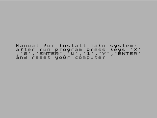
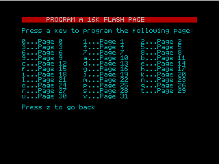
First, copy the file esx89f12.tap from the download package to the root directory of a CF card. This card should be in FAT16 or FAT32 format and may already contain files. Remove the card from the PC and insert it into the DivIDE Plus. Power up the Spectrum by holding down the space bar. The current firmware on the first bank is re-initialised and recognises the new CF card. Next, press the NMI button on the DivIDE Plus. The newly copied file esx89f12.tap is selected in the NMI file menu and started. The following unspectacular screen will appear:
 At this point you have 2 choices: If you want to install ESXDOS now, press ENTER to proceed to the flash utility. Alternatively, press N to load the
next ROM file, which is located in the file esx89f12.tap. In this case, FATware12a would be loaded next and the same menu would be offered again.
There are no more ROM files and pressing N again will effectively rewind the TAP file and reload ESXDOS.BIN.
At this point you have 2 choices: If you want to install ESXDOS now, press ENTER to proceed to the flash utility. Alternatively, press N to load the
next ROM file, which is located in the file esx89f12.tap. In this case, FATware12a would be loaded next and the same menu would be offered again.
There are no more ROM files and pressing N again will effectively rewind the TAP file and reload ESXDOS.BIN.
Now install ESXDOS (as shown in the picture) and press ENTER to start the flash utility.
 Before we get down to business, a compact guide to installing the first firmware (referred to here as the main system) will appear. The installation is done in exactly the
same way in the following steps. In addition, the next bank should also be programmed with a different firmware.
Before we get down to business, a compact guide to installing the first firmware (referred to here as the main system) will appear. The installation is done in exactly the
same way in the following steps. In addition, the next bank should also be programmed with a different firmware.
Press any button to continue.
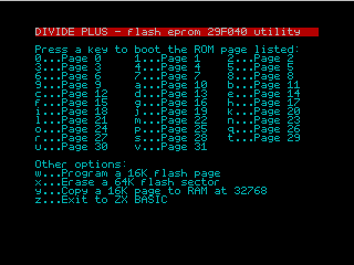 This is how the flash utility looks when started. A memory sector must be erased before new firmware can be installed. This is done by pressing the X (Erase) button.
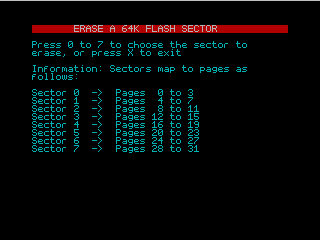 This screen shows the Erase menu. Press button 0 to erase sector 0 without any further prompt. During this process, which takes about a second, the message
Erasing... appears and when it is finished, Done! Incidentally, sector 0 contains the firmware 0 and 2.
This screen shows the Erase menu. Press button 0 to erase sector 0 without any further prompt. During this process, which takes about a second, the message
Erasing... appears and when it is finished, Done! Incidentally, sector 0 contains the firmware 0 and 2.
Important: The DivIDE Plus can no longer boot in this state after a reset. Continue quickly and press ENTER (or another key) to return to the main
menu. Press the W button to open the program menu.
 This screen shows the program menu. The new firmware must now be written to page 1 using button 1. This process also starts without a prompt and is confirmed by the message
Writing flash chip... After a few seconds the message Done! should appear. Press ENTER (or another key) to return to the main
menu.
This screen shows the program menu. The new firmware must now be written to page 1 using button 1. This process also starts without a prompt and is confirmed by the message
Writing flash chip... After a few seconds the message Done! should appear. Press ENTER (or another key) to return to the main
menu.
This means that ESXDOS is the first firmware installed in the flash memory, but it will not work yet because some components on the CF card are still missing (or not up to date in the case of an update). For this reason it makes sense to switch off the Spectrum at this point and connect the CF card to the PC. Copy the 4 directories BIN, DOCS, SYS and TMP from the download package to the main directory of the CF card. Put the prepared card back into the Divide Plus and power on the Spectrum by holding down the space bar. ESXDOS should now start and briefly display the correct version number.
The same sequence applies to updating ESXDOS: first replace the ROM file in the flash memory, then replace the files in the BIN, DOCS,
SYS and TMP directories on the CF card.
The installation is not complete as the firmware on pages 2 and 3 was also removed when memory sector 0 was erased. FATware is now to be installed here, so the esx89f12.tap file needs to be restarted. This can be done using the newly installed ESXDOS and its NMI menu.
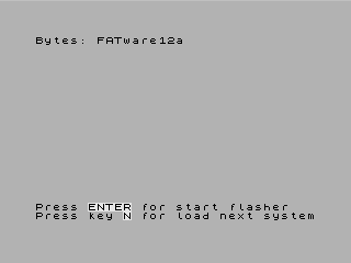 Here the installer has been started and the next ROM file FATware12a has already been loaded with N. Now press ENTER to
proceed to the next page and press ENTER again to proceed to the Flash Utility. Do not erase the sectors at this stage and press W to go straight to
the program menu.
Here the installer has been started and the next ROM file FATware12a has already been loaded with N. Now press ENTER to
proceed to the next page and press ENTER again to proceed to the Flash Utility. Do not erase the sectors at this stage and press W to go straight to
the program menu.
This screen shows the program menu again. Unlike the first firmware, the new firmware must now be written to page 3 using button 3. This process will start again with the
message Writing flash chip... and end a few seconds later with the message Done! Press ENTER (or another key) to return to the
main menu and press Z to exit the flash utility.
This completes the installation. For a final test of FATware, stop the BASIC program with BREAK, switch to the newly installed FATware with OUT 23,2
and start an initialisation with PRINT USR 0. After pressing ENTER to execute, you must be quick and press the space bar immediately so that FATware
can read the CF card again.
The installation package also includes the esx89f14.tap installer. This contains ESXDOS 0.8.9 and the relatively recent FATware 0.14a3. However, FATware versions 0.14 and above have the peculiarity of requiring an additional file on the CF card. This file is loaded during initialisation and switches the Divide Plus into MAPRAM mode. If FATware is installed as Firmware 2 (as described above), this will work fine until a spectrum reset is required. The DivIDE Plus will then switch back to firmware 0 (ESXDOS in this case), but will leave the MAPRAM mode active and this will inevitably cause a crash which can only be recovered by briefly switching off the power supply.
If you still want to use FATware 0.14a3, I recommend installing it as the first firmware (contrary to the instructions above). To do this, copy the FATware directory from the installation package to the main directory of the CF card. FATware is then started by holding down the space bar and after successful initialisation the NMI menu is also available so that further firmwares can be installed.
With FATware as the first firmware, a reset with active MAPRAM mode will always return to FATware and the system will remain alive. However, when changing to another firmware, the MAPRAM mode must first be switched off with OUT 23,192 and then the desired firmware must be selected with the corresponding OUT 23,x. After returning to FATware (either by reset or with OUT 23,0), initialisation is required again.
| midimon-v10.zip | Simple MIDI Monitor - Simple MIDI monitor for the ZX Spectrum Next and the Next MIDI Box |
 This program, written in NextBASIC, demonstrates the MIDI capabilities of the ZX Spectrum Next with a Next MIDI Box connected. It analyses the data received
via MIDI In and displays it clearly in the form of a list. First connect the Next MIDI Box to the JOY 2 port of the ZX
Spectrum Next. Then connect the MIDI Out of the MIDI instrument whose data you want to analyse to the MIDI In of the
Next MIDI Box.
This program, written in NextBASIC, demonstrates the MIDI capabilities of the ZX Spectrum Next with a Next MIDI Box connected. It analyses the data received
via MIDI In and displays it clearly in the form of a list. First connect the Next MIDI Box to the JOY 2 port of the ZX
Spectrum Next. Then connect the MIDI Out of the MIDI instrument whose data you want to analyse to the MIDI In of the
Next MIDI Box.
When the program is launched, it starts working immediately. Incoming MIDI messages are immediately analysed and displayed. However, there are a few exceptions that will not appear in the output. These are listed below. The program is kept very simple and there is only one way to intervene in the process: Pressing and holding the space bar pauses the output until the key is released.
The program works well as long as you are not sending large amounts of data. For example, you can use it to analyse the output of a keyboard or MIDI controller, but not the data sent by a MIDI file
player. There is so much information that the output cannot be read in any meaningful way, and the receive buffer is likely to overflow and data will be lost.
The fact that this BASIC program is able to receive and process MIDI data in real time is due to the ZX Spectrum Next's ability to send and receive serial data independently of the CPU: the UART (Universal Asynchronous Receiver Transmitter). This is also equipped with a 256-byte receive buffer, so that further data can be received in the background, even when the program is temporarily very busy. When the program is free again, more bytes can be retrieved from the buffer and the backlog processed. However, it is not impossible for the buffer to overflow. The program detects this state and displays a message. In this case, data will be lost.
In detail, the program does the following: Firstly, the joystick port 2 (JOY 2) is set to UART mode via a Next register. This setting gives the pins 7 and 9 the function of UART-TX (transmitter) and UART-RX (receiver). The UART normally connected to the WiFi module is then redirected to the joystick port via a Next I/O port. The UART is first initialised via another Next I/O port and then set to 8N1 (8 data bits, no parity bit and 1 stop bit). The final step is to program the UART to the MIDI speed of 31250 baud. However, this is a bit more complex: the UART clock is derived from the system clock of the video signal generation and is between 27 MHz and 33 MHz, depending on the video mode set. Therefore, the current video mode (0-7) has to be determined via a Next register, then the corresponding clock frequency (documented in the ZX Spectrum Next manual) can be used as clock base and divided by 31250. The result is the prescaler value, which can then be used to set the UART to the correct speed. This in turn requires the division of the prescaler value into two 7-bit values, which are then sent in sequence to the UART via a Next I/O port. Before the program starts to work, a few variables are set, graphics layer 1.1 is activated and the system is switched to 28 MHz.
The main loop of the program first uses a Next I/O port to check if there is new data in the receive buffer. It also checks for a buffer overflow and displays a message if necessary. If the space bar is pressed, the program stops at that point until the key is released. If a byte has been read from the buffer, further processing depends on whether it is a status byte or a data byte. In the case of a status byte (indicated by bit 7 being set), the messages that require further data bytes are processed first. Here the status is stored, the number of expected data bytes is defined, a byte counter is cleared and then the system waits for further bytes. Status messages that do not require further data are output directly or ignored (see below).
When processing data bytes, a counter is used to determine which byte has been received, and then the byte is buffered in the correct position. Once the last byte of a MIDI message has been received, processing of the entire message begins. For all channel messages, the MIDI channel is determined first. For messages with note values, the octave is then calculated (note value divided by 12). The note number within the octave is then determined using a modulo operation and the corresponding name is read from a string containing the 12 note names, e.g. C# (C sharp). All other data bytes, such as velocity, controller numbers, controller values or program numbers, are simply output as a 3-digit numerical value. An exception is Pitch Bend, where all values are 4 digits and have a sign. Another exception is System Exclusive, where only the number of bytes is counted and then the total is output.
The following table lists all the messages that the MIDI Monitor can display:
| Bytes | Messsage | Parameters displayed | Colour |
|---|---|---|---|
| 8X XX XX | Note Off | MIDI channel (C01...C16), Note value (C-0...G-9), Release value (0...127) | Magenta |
| 9X XX XX | Note On | MIDI channel (C01...C16), Note value (C-0...G-9), Velocity value (0...127) | Red |
| AX XX XX | Polyphonic Aftertouch | MIDI channel (C01...C16), Note value (C-0...G-9), Aftertouch value (0...127) | Cyan |
| BX XX XX | Control Change | MIDI channel (C01...C16), Controller number (0...127), Controller value (0...127) | Blue |
| CX XX | Program Change | MIDI channel (C01...C16), Program number (0...127) | Green |
| DX XX | Channel Aftertouch | MIDI channel (C01...C16), Aftertouch value (0...127) | Cyan |
| EX XX XX | Pitch Bend | MIDI channel (C01...C16), Value (-8192...+8191) | Blue |
| F0 ... F7 | System Exclusive | Number of bytes transferred | Red |
| F3 XX | Song Select | Song number (0...127) | Black |
| F6 | Tune Request | Black | |
| FA | Start | Black | |
| FB | Continue | Black | |
| FC | Stop | Black | |
| FF | System Reset | Black |
The application can also handle the so-called running status. MIDI allows data bytes to be sent without a leading status byte, provided the status has not changed. The program recognises such data bytes and displays the complete message. There is a special case for note values: Note numbers 0-11 are not defined and the text Low is displayed instead of the note value.
Some MIDI messages are sent at very short intervals, so that it is not possible to display them in the MIDI Monitor. The following messages are therefore analysed internally but not displayed:
| Bytes | Message |
|---|---|
| F1 XX XX | MIDI Time Code |
| F2 XX XX | Song Position Pointer |
| F8 | Timing Clock |
| FE | Active Sensing |
The joystick port defined in the program can also be changed to JOY 1. This is done by commenting out a line at the beginning of the program. In principle, it is also possible to use UART 1 of the accelerator board instead of UART 0 of the WiFi module. However, this would require some changes. Important: Once the application has started, UART 0 is connected to the joystick port and no longer to the WiFi module. It is therefore not possible to use MIDI and WiFi at the same time. If you need the WiFi function again, simply reset the ZX Spectrum Next and the UART will return to its original state.
This program can be extended. For example, it would be possible to add a timestamp to each message and to save the screen output to a file. The data display could also be extended: the controller numbers defined in the MIDI standard could be displayed in plain text, as well as the program numbers, which have fixed names in General MIDI, for example. Maybe there will be a version 2.0...
| github.com/UzixLS/zx-midiplayer/tree/master | This is the Github page of the ZX MIDI Player. Here you will always find the current source code of this project, as well as a finished release with the executable player as a TR-DOS image at irregular intervals. |
| zx-midiplayer-tap.zip | If the latest version is not available on Github, or the assembly is too complicated, you can download the latest version as a TAP file here. This package contains version 3.9, dated 24 May 2025. |
 This MIDI player runs on all variants of the ZX Spectrum 128 and also on the ZX Spectrum Next. It plays standard MIDI files (type 0 and 1) and can output the MIDI data to various hardware. Many
storage devices are supported: Apart from TR-DOS, which is permanently installed, you can also use DivIDE and DivMMC. It is also possible to run the player with a higher system clock (up to 28 MHz).
The only limitation is that the MIDI file size must not exceed 64kB.
This MIDI player runs on all variants of the ZX Spectrum 128 and also on the ZX Spectrum Next. It plays standard MIDI files (type 0 and 1) and can output the MIDI data to various hardware. Many
storage devices are supported: Apart from TR-DOS, which is permanently installed, you can also use DivIDE and DivMMC. It is also possible to run the player with a higher system clock (up to 28 MHz).
The only limitation is that the MIDI file size must not exceed 64kB.
The current version of the ZX MIDI Player can be downloaded as assembler source code from the Github homepage. An executable version is also available as a TR-DOS image, but this is not always up to date. You can use this version on a ZX Spectrum 128 with DivIDE or DivMMC (both with ESXDOS). However, it is not suitable for the ZX Spectrum Next, as you have to switch the Next to ZX Spectrum 128 or +2 mode first. A TAP file that can be loaded directly in Next mode would be better.
There is a solution: You can assemble the current source code into a finished program on a PC using the versatile Z80 assembler sjasmplus. This creates a TR-DOS image as well as a TAP and SNA file. I have taken the current version of the MIDI player as a basis and made the generated TAP file available for download: zx-midiplayer-tap.zip. In the future I will check if a new version of the player has been released and then update the TAP file.
In the TRD version, when you start the player, a kind of browser appears, allowing you to navigate through drives and directories, as well as change settings. Starting the TAP version first takes you to the player, where a short demo song is played. The player will then automatically switch to the browser view. In this browser, you can use the Space bar to switch between the Menu and Entries windows. In the active window, you can move the cursor with the arrow keys and press Enter to activate the selected item.
With this knowledge, you can now make some settings. Firstly, you need to specify which hardware you want to use to output MIDI data. To do this, go to Settings in the left window, with Output already selected in the right window. Press Enter to select the desired setting. If you are using a ZX Spectrum 128 and the internal RS232/MIDI port, the default setting of 128 std is just right. On the ZX Spectrum Next, select ZX Next UART. The MIDI data is then output to the Next MIDI Box via the joystick port.
Another setting concerns the file system. If you are using TR-DOS, no action is required. If you are using a DivIDE or DivMMC, you need to enable the
appropriate option in the menu. On a ZX Spectrum Next it is necessary to enable DivMMC. Normally you would select the Save option to save the settings.
However, this only works under TR-DOS and means that you have to repeat the setting each time you start the program on other systems. Especially for the ZX Spectrum Next you can find an
unofficial version of TAP in the package zx-midiplayer-tap.zip, which will start with the correct settings. The last step is important: Apply the
settings and an additional drive letter should appear in the left window (there can be several drive letters). This can be used to navigate through the file system and select the MIDI files you want
to play.
If you want to assemble the source code yourself, here is a short guide: You need the source code of the ZX MIDI Player and the assembler package sjasmplus (download the latest Windows version from Releases). Unpack the source into an empty directory. Only the file sjasmplus.exe from the sjasmplus package is required, and is best copied to a directory in the PATH system variable. Alternatively, you can simply copy it to the source directory where the make.bat file is located. You can then run make.bat. You will get some errors because the Github environment is missing. However, the build itself should run without errors. This is indicated by the messages Pass 1 complete (0 errors), Pass 1 complete (0 errors) and Pass 3 complete Errors: 0, warnings: 2 .... The two warnings can be ignored and are caused by 2 empty strings in make.bat which should contain the version number. You will now find a new subdirectory build, containing the finished files in SNA, TAP and TRD format that you can run on the Spectrum.
The development continues and there is now a modified MIDI player, adapted to the +3DOS, which is used in the ZX Spectrum +3 and also in the ZX Spectrum Next. Everything else is the same as the player described above. The modified player has the great advantage that all settings can be saved, as the original version can only do this under TR-DOS. There is also a special version for the ZX Spectrum Next, which already has the optimum presets (MIDI output to Next MIDI Box and enabled DivMMC file system). Furthermore, +3DOS is only used here for writing and reading the configuration.
The complete assembler source code is available via GitFlic (see table), but you have to assemble it yourself. To do this, you need the sjasmplus assembler mentioned above and preferably a Linux environment to build the executable program. I have already done this work and the finished versions for the ZX Spectrum +3 and the ZX Spectrum Next can be downloaded from the following table. I will also check regularly for updates and then update the programs.
| https://gitflic.ru/project/chwe/zx-midiplayer | This is the GitFlic homepage of the modified ZX MIDI Player for the ZX Spectrum +3 and ZX Spectrum Next. Here you can download the current source code of the project, the executable player has to be built by yourself. |
| zx-midiplayer-plus3.zip | This package contains the modified ZX MIDI Player as an executable version for the ZX Spectrum +3. In addition to the files in +3DOS format, a disc image is also included. |
| zx-midiplayer-next.zip | This package contains the modified ZX MIDI Player as an executable version for the ZX Spectrum Next. |
There is another version of the ZX MIDI Player that has been optimised for use on systems running ESXDOS. This version can be used on all DivIDE and DivMMC systems running ESXDOS, as well as on the ZX Spectrum Next. This means that these systems also have the option of saving all settings in the file system.
| https://codeberg.org/jamesh/zx-midiplayer/releases | You can download the source code and two finished programmes from this page. Although these are preliminary versions, they run stably. The zxmidipl.esxdos.zip file contains the ZX MIDI Player for ESXDOS (DivIDE and DivMMC), and the zxmidipl.zxn.zip file contains an optimised version for the ZX Spectrum Next. |
Many thanks to Eugene Lozovoy for creating this excellent MIDI player, and to Chwe and Jamesh for adapting it for use with the +3, Next and ESXDOS.