


On this page I present modifications and conversions that improve some features of the Sinclair computers. Most of them require a good knowledge of electronics and some experience, because although the Spectrum computers are quite robust, a little carelessness can easily damage the computer. This starts with opening the case: the keyboards are always connected via thin foil connectors, which are very fragile. So you really should know what you are doing - I am not liable for any damage!
 Table of contents
In its original state, the ZX Spectrum 48k only offers a TV output for connecting a TV set via a UHF channel. Unfortunately, with today's televisions, this only delivers a mediocre picture, and in some cases no usable picture at all, so there is definitely room for improvement here.
A video output (FBAS) provides a significant improvement. The signal is already present in the Spectrum and can be tapped directly at the input of the modulator. The mechanical construction is a bit more difficult than the electronic part.
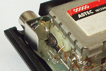 I used an RCA socket for the PCB mounting, bent the terminals to fit and soldered the ground connection to the side of the modulator housing. This provides a secure ground connection and a high
degree of mechanical stability. I also used a lot of two-component adhesive to fix the socket to the PCB.
I used an RCA socket for the PCB mounting, bent the terminals to fit and soldered the ground connection to the side of the modulator housing. This provides a secure ground connection and a high
degree of mechanical stability. I also used a lot of two-component adhesive to fix the socket to the PCB.
Now all that's left is to connect the inner conductor of the RCA socket to the modulator input with a short wire - and that's it.
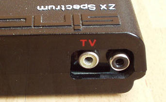 If you work carefully, the extra socket fits very well next to the modulator.
By the way, you can often find a circuit on the net with an additional transistor in a collector circuit that works as a video amplifier. This circuit has been tested, but I get a better picture on
my LCD monitor when I use the output directly.
A very important function is missing on the ZX Spectrum: the reset button. This is not because it crashes all the time and needs to be restarted, but because many programs (especially games) do not allow you to return to the BASIC operating system. It is possible to restart the computer by turning off the power, but this is not a good solution.
 A reset button is relatively easy to retrofit. Any model of button that makes a contact when pressed and opens when released can be used.
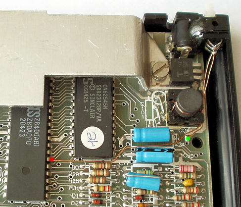
I glued my button to the side of the power connector using two-component adhesive. The button is facing backwards (unfortunately it is hard to see here).
The button is connected to ground (green dot) and the reset pin of the Z80 - pin 26 (red dot). You have to be careful though, because there are different versions of the board, some of which are very different, i.e. a suitable ground point may not be in the position shown. If in doubt, use the middle terminal of the voltage regulator (7805).
The picture opposite shows an Issue 4a board.
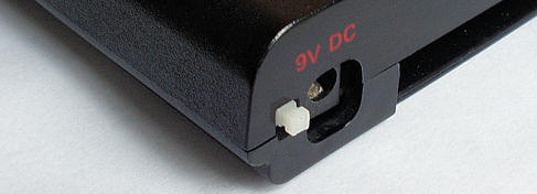 Here you can see the button inside the closed case. Normally a cap should be placed on it, but this way it is less obvious and still easy to use.
Compared to the ZX Spectrum, the ZX Spectrum 128k has a video output (FBAS) and an RGB output as standard. The additional connectors are located on an 8-pin DIN socket. If you are lucky enough to have a monitor or TV with an RGB input, you should definitely use RGB for best results.
 Part 1: Unfortunately, my LCD monitor only has a composite video input, so I have to use the video output. If you connect a ZX Spectrum 128k in its original state, the result
is very bad.
Part 1: Unfortunately, my LCD monitor only has a composite video input, so I have to use the video output. If you connect a ZX Spectrum 128k in its original state, the result
is very bad.
Two components are mainly responsible for this: D35 and R144 (shown in red). These two components must be removed. It is also sufficient to desolder a connection on one side or to break the connection. After this action the picture is much better.
Why these two parts were supplied is not entirely clear to me. The successor models (e.g. ZX Spectrum +2) do not have these parts and have a better picture right from the start.
 Part 2: With the ZX Spectrum 128k and all its successors, the audio signal from the beeper and sound chip is modulated and then mixed with the video signal so that it can be
transmitted to the TV set via the modulator. Unfortunately, this results in a small amount of interference in the video picture.
Part 2: With the ZX Spectrum 128k and all its successors, the audio signal from the beeper and sound chip is modulated and then mixed with the video signal so that it can be
transmitted to the TV set via the modulator. Unfortunately, this results in a small amount of interference in the video picture.
The diagram opposite shows the circuit for generating the audio carrier signal. Capacitor C126 (framed in red) couples the carrier signal into the video signal. The interference from the audio signal can be eliminated by removing C126 or breaking the connection.
This should only be done if you can do without the TV output (modulator). The audio signal will then no longer be transmitted.
I received this tip from Ingo Truppel, many thanks to him.
If you connect the ZX Spectrum 128k to a monitor via RGB or Video/FBAS, the sound is unfortunately missing. Although the sound signals are available at the „MIC“ socket, this has two disadvantages: The sound outputs are poorly tuned, i.e. the beeper is quite loud and the sound chip is very quiet. Also, if you use a cassette recorder, you have to plug it in and out all the time.
It is therefore essential to retrofit a proper sound output. You can either convert an unused connection on the RGB socket (e.g. VSYNC on pin 5) or install an additional socket.
 I decided to use an additional RCA socket, which fits very well between the RGB connector and the modulator. I bent it (like the video output of the ZX Spectrum) and soldered it to the modulator with
the ground connection.
I decided to use an additional RCA socket, which fits very well between the RGB connector and the modulator. I bent it (like the video output of the ZX Spectrum) and soldered it to the modulator with
the ground connection.
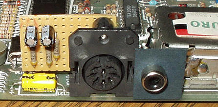
The picture also shows a small breadboard. It contains a circuit of 3 resistors and 2 capacitors to control the volume of the beeper/MIC/EAR and sound chip audio sources.
 The additional circuit is shown in red. The resistors of the two signal sources (39k and 3.3k) are dimensioned so that the volume levels of the beeper and the sound chip are approximately the same.
The two capacitors separate the DC component from the MIC/EAR and the sound chip amplifier.
The additional circuit is shown in red. The resistors of the two signal sources (39k and 3.3k) are dimensioned so that the volume levels of the beeper and the sound chip are approximately the same.
The two capacitors separate the DC component from the MIC/EAR and the sound chip amplifier.
The 5 components can be mounted on a small breadboard or, if required, freely wired without a board.
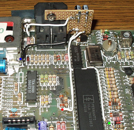 Here you can see a part of the mainboard of the ZX Spectrum 128k. I connected the sound chip signal to C125 (red dot) and the beeper/MIC/EAR signal to D13 (green dot). The ground wire can be soldered
to the modulator case (blue dot). The sound output is then routed directly from the breadboard to the additional RCA socket.
Here you can see a part of the mainboard of the ZX Spectrum 128k. I connected the sound chip signal to C125 (red dot) and the beeper/MIC/EAR signal to D13 (green dot). The ground wire can be soldered
to the modulator case (blue dot). The sound output is then routed directly from the breadboard to the additional RCA socket.
The unused screw hole of the RGB socket can be used to mount the board.
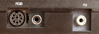 If you work well, the extra socket is barely noticeable.
There are several versions of the ZX Spectrum 128k. In my earlier active days I had a model where the RS-232/MIDI interface was designed as a D-Sub socket. Although this was not wired according to the standard, it had the great advantage that suitable connectors were available. On the other hand, you need a strange 6-pin connector for the keypad, which you can't seem to find anywhere.
Today I own a ZX Spectrum 128k where both the RS-232/MIDI and the keypad are attached to such a strange 6-pin connector. You can do without the keypad, but I want to use the RS-232/MIDI interface, so I decided to install an extra connector.
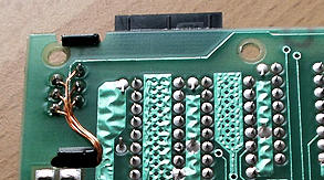
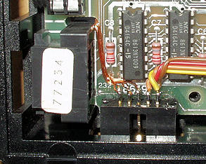 Box connectors with a 2.54mm pitch are quite common, so a 10-pin connector of this type was chosen. It not only provides space for the RS-232/MIDI signals, but also for all the keypad connections, as
well as ground and +12V.
Box connectors with a 2.54mm pitch are quite common, so a 10-pin connector of this type was chosen. It not only provides space for the RS-232/MIDI signals, but also for all the keypad connections, as
well as ground and +12V.
The connector was glued to the front left of the PCB and the case was slightly modified at this point. This position was basically predetermined, as the previous owner of the computer had installed a
video socket there, which became superfluous as a result of the measures described above.
 Here you can see the same spot from below. The connections from the RS-232/MIDI port to the new connector were made with 0.3mm enamelled copper wire.
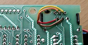 A piece of ribbon cable was used for the slightly longer cables from the keypad.
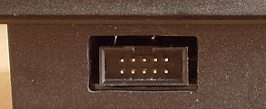 This is how the connection looks when the case is closed. Of course, the connector would be better placed on the left or the back, but the previous owner had left an ugly hole there.
The pin assignment is shown in the table below. A new standard may be established :-)
| Pin new | Pin old | Function | Direction |
|---|---|---|---|
| 1 | Keypad [2] | Spectrum → Keypad | |
| 2 | Keypad [3] | Spectrum ← Keypad | |
| 3 | Keypad [4] | Spectrum → Keypad | |
| 4 | Keypad [5] | Spectrum ← Keypad | |
| 5 | RS-232 [2] | RXD | Spectrum ← Device |
| 6 | RS-232 [3] | TXD | Spectrum → Device |
| 7 | RS-232 [4] | CTS | Spectrum ← Device |
| 8 | RS-232 [5] | RTS, MIDI Out | Spectrum → Device |
| 9 | RS-232 [1] | Ground | |
| 10 | RS-232 [6] | +12V via 180 Ohm |
 The circuit opposite shows how to make an adapter cable for a near-standard RS-232 interface.
 And this is what a MIDI out cable looks like. You can use either a DIN plug or a jack. If you use a plug, you can connect your MIDI equipment directly (use MIDI In). If you use a jack or coupling,
you will also need a standard MIDI cable. The resistor is required to limit the MIDI interface current to 5mA.
And this is what a MIDI out cable looks like. You can use either a DIN plug or a jack. If you use a plug, you can connect your MIDI equipment directly (use MIDI In). If you use a jack or coupling,
you will also need a standard MIDI cable. The resistor is required to limit the MIDI interface current to 5mA.
Although the ZX Spectrum +2 is a vast improvement on its predecessor, there are still some weaknesses that could be addressed.
 Part 1: The transistor TR4 (2N3904 - shown in red) used here has too low a current gain, which can lead to a very poor and unstable picture. If you are not satisfied with the
picture, you should replace this transistor with a similar type with a higher current gain, e.g. BC548C.
Part 1: The transistor TR4 (2N3904 - shown in red) used here has too low a current gain, which can lead to a very poor and unstable picture. If you are not satisfied with the
picture, you should replace this transistor with a similar type with a higher current gain, e.g. BC548C.
The transistor is located behind the RGB connector, so it is easy to find on the board.
This tip comes from Ingo Truppel, thanks a lot.
 Part 2: The problem is the same as with the ZX Spectrum 128k - the audio signal from the beeper and sound chip is modulated and mixed with the video signal so that it can be
sent to the TV via the modulator. Unfortunately, this results in a slight interference in the video picture.
Part 2: The problem is the same as with the ZX Spectrum 128k - the audio signal from the beeper and sound chip is modulated and mixed with the video signal so that it can be
sent to the TV via the modulator. Unfortunately, this results in a slight interference in the video picture.
The diagram opposite shows the circuit for generating the audio carrier signal. Capacitor C31 (shown in red) couples the carrier signal into the video signal. The interference from the audio signal can be eliminated by removing C31 or breaking the connection.
This should only be done if you can do without the TV output (modulator). Audio signals will then no longer be transmitted.
Thanks again to Ingo Truppel for this tip.
The ZX Spectrum +2 has a sound output as standard. This is initially very positive, but the volume levels of the sound sources are very different: the sound chip is much too quiet, the beeper too loud and the cassette recorder terribly loud when loading a program. This can be easily adjusted by replacing 3 resistors.
 The diagram opposite shows how the 3 sources EAR, MIC/beeper and sound chip are mixed. Changing the resistors shown in red as follows will result in a better adjusted volume ratio:
Replace R80 with 330k (for EAR)
Replace R45 with 39k (for MIC and beeper)
Replace R37 with 3.3k (for sound chip)
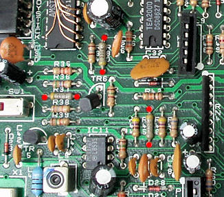 This picture shows a part of the board of the ZX Spectrum +2. You can see the resistors to be replaced and the soldering points are marked with a red dot.
Above: Replace R80 with 330k
Left: Replace R37 with 3.3k
Right: Replace R45 with 39k
1. Connection sockets
When I first plugged in my ZX Spectrum +2 and started it up, I noticed that the connectors were wobbly. This mainly affected the two joystick connectors, the RGB connector and the two RS-232 and keypad connectors. Especially with the joysticks, which can only be plugged in and out with a lot of force, you can expect the construction to give way and the contacts to break.
So I used my two-component adhesive (mentioned several times) and glued all the affected sockets to the main board. This means that the sockets can also be used as carriers for other connectors or control elements, as you can see below.
2. Joystick connectors
Somehow I couldn't get my old Spectravideo joystick to work on the ZX Spectrum +2. Only one direction worked on both ports. Should the joystick ports be broken? No, everything is fine. Amstrad has changed the pin assignment so that all classic joysticks will not work on the ZX Spectrum +2 without an adapter. Since I have a Spectravideo and other joysticks and interfaces with the old assignment, I decided to change the joystick ports on the ZX Spectrum +2.
First, I removed all connections to the joystick sockets. I then rewired port 1 as a cursor joystick. I also built a small circuit board with a Kempston interface, screwed it into the unused mounting hole of the RGB connector and wired port 2 as a Kempston joystick. I also connected +5V to both connectors so that joysticks with built-in electronics could be used. I have not documented this change here as it is quite complex and tricky.
3. RS-232 and keypad
The same applies to these two connectors as for the ZX Spectrum 128k, where I described the installation of a new connector in detail. On the ZX Spectrum +2 the extension is a bit easier as the two connectors are next to each other on the board and the new connector can simply be glued to the keypad connector (see picture below).
4. ROM switch
The ROM of the ZX Spectrum +2 has been changed compared to the ZX Spectrum 128k. This can be seen in the changed copyright messages (Amstrad instead of Sinclair) and the absence of the tape tester in the main menu. I have not been able to find out if other things have been changed, but many addresses (e.g. of the RS-232 routines) have been moved.
In case of compatibility problems, I have removed the original ROM and replaced it with a 27C512 EPROM. This has twice the memory capacity (64kB) and can hold the contents of both the original Amstrad ROM and the ZX Spectrum 128k ROM. An additional switch glued to the RS-232/MIDI socket allows you to switch between the two systems. I have not documented this modification here either, as the benefit is probably relatively small.
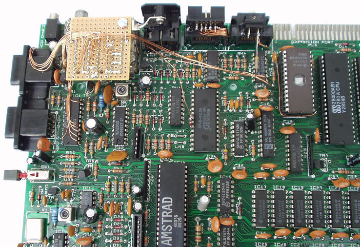
This is what the board of my ZX Spectrum +2 looks like after all the modifications:
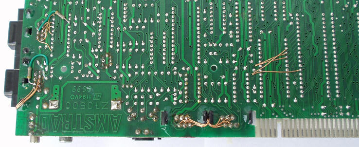
The underside of the board has also changed slightly:
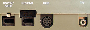 On the rear panel, the only signs of changes are the two extra cut-outs above the RS-232/MIDI and keypad connectors.