


On this page I present modules and hardware expansions for the ZX Spectrum. A good knowledge of electronics and some experience are required for the assembly, because although the Spectrum computers are quite robust, a little carelessness can damage the computer. Before connecting any of the following circuits to the Spectrum, check all connections carefully to ensure there are no short circuits. I am not responsible for any damage!
 Table of contents
| ZX Interface 2 - ROM module with 32 banks |
| ZX Spectrum 128k - MIDI cable |
| Next MIDI Box - MIDI interface for the ZX Spectrum Next |
As well as 2 joystick connectors, the ZX Interface 2 also has a ROM port hidden under a hinged cover. Modules with games can be inserted here, which has the great advantage that you can start playing as soon as you switch on the computer. A total of 10 games were released as ROM modules, but these were relatively expensive compared to the cassette version. Unfortunately, these cartridges are hard to come by these days, but that's not a bad thing as you can make one yourself. At this point I would like to refer you to the website www.fruitcake.plus.com, which has a lot of information about the ROM modules available at the time and how to build your own. This site also inspired me to build my version of the module, which is equipped with a 29F040 Flash ROM and has space for 32 ROM banks:
 The diagram opposite shows the schematic of the ROM module. The technique is relatively simple: All data lines from the ROM port D0-D7 are connected to the corresponding pins
on the Flash ROM, as well as the address lines A0-A13, ground and +5V power supply. The two address lines A14 and A15 are
connected to an OR gate (IC2) which acts as an address decoder. The output goes to the ROM pin /CE and only enables the ROM when A14 and
A15 are at low level. This means that the ROM always operates in the address range 0-3FFFH (0-16383) - just like the Spectrum's internal ROM. To avoid conflicts with the
internal ROM, the ROMCS line is set to +5V, thus disabling the Spectrum's internal ROM. The /MREQ line is also worth mentioning - this leads to
/OE of the ROM and ensures that the outputs of the ROM are only activated when memory is accessed.
The diagram opposite shows the schematic of the ROM module. The technique is relatively simple: All data lines from the ROM port D0-D7 are connected to the corresponding pins
on the Flash ROM, as well as the address lines A0-A13, ground and +5V power supply. The two address lines A14 and A15 are
connected to an OR gate (IC2) which acts as an address decoder. The output goes to the ROM pin /CE and only enables the ROM when A14 and
A15 are at low level. This means that the ROM always operates in the address range 0-3FFFH (0-16383) - just like the Spectrum's internal ROM. To avoid conflicts with the
internal ROM, the ROMCS line is set to +5V, thus disabling the Spectrum's internal ROM. The /MREQ line is also worth mentioning - this leads to
/OE of the ROM and ensures that the outputs of the ROM are only activated when memory is accessed.
In contrast to the original ROM modules, which are equipped with a 16kB ROM, a Flash ROM with a capacity of 512kB is used here. This allows 32 banks of 16kB each to be implemented. To switch the
banks, the upper address lines A14-A18 of the Flash ROM are connected to switches. A 16-way rotary encoder switch is used, which outputs the current switch position as a
hexadecimal value - just right for controlling the address lines A14-A17. The remaining line A18 can be selected using a dip-switch. This provides 2
areas with 16 banks each.
| Quantity | Part | Number | Remark |
|---|---|---|---|
| 1 | IC 29F040B | IC1 | Flash ROM, e.g. AM29F040B, DIP version |
| 1 | IC 74LS32 | IC2 | DIP version |
| 5 | Resistor 5.6kΩ | R1-R5 | Metal |
| 2 | Capacitor 100nF | C1, C2 | Ceramic |
| 1 | Encoder switch | S1-S4 | Rotary encoder switch 16-way, e.g. Reichelt „KMR 16“ |
| 1 | DIP switch | S5 | DIP switch, e.g. Reichelt „NT 02“ |
| 1 | IC socket 32-pin | (IC1) | DIL 32-pin |
| 1 | IC socket 14-pin | (IC2) | DIL 14-pin |
| 1 | Breadboard | Breadboard, grid 2.54mm, about 50mm x 50mm | |
| 1 | Contact strips | can be cut from an old PC ISA board |
Other Flash ROMs or EPROMs can also be used instead of the 29F040B, as the pin assignment is usually compatible. If in doubt, consult the datasheet. I chose this Flash ROM because it is cheaper than a comparable EPROM. Flash ROMs are also much easier to erase and reprogram if a suitable programmer is available.
Individual switches can be used instead of the encoder switch. In this case you have to select the desired bank in hex code, but this should not be a problem for real Spectrum fans :-)
 I built the ROM module on a small breadboard. The connector is a bit tricky: I had some strips left over from a previous project. One of them was simply glued to the breadboard (with two-component
adhesive). If you don't have such strips, you can recycle them from old PC ISA boards. If you know how to etch circuit boards, you are best off. In this case, the strips are simply integrated into
the PCB layout. A layout is given on the above page, but it would have to be modified slightly.
I built the ROM module on a small breadboard. The connector is a bit tricky: I had some strips left over from a previous project. One of them was simply glued to the breadboard (with two-component
adhesive). If you don't have such strips, you can recycle them from old PC ISA boards. If you know how to etch circuit boards, you are best off. In this case, the strips are simply integrated into
the PCB layout. A layout is given on the above page, but it would have to be modified slightly.
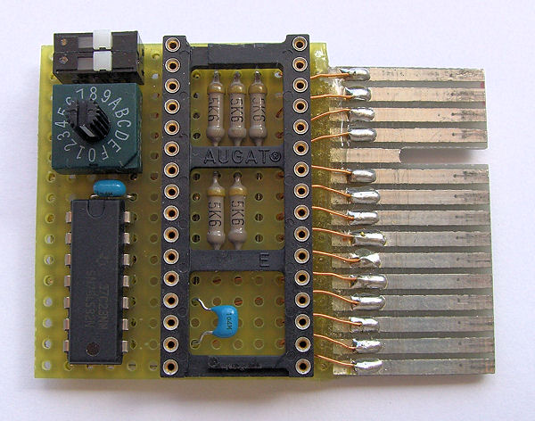
To make the board as small as possible, I have placed some components under the ROM. These are the 5 resistors and the capacitor C1.
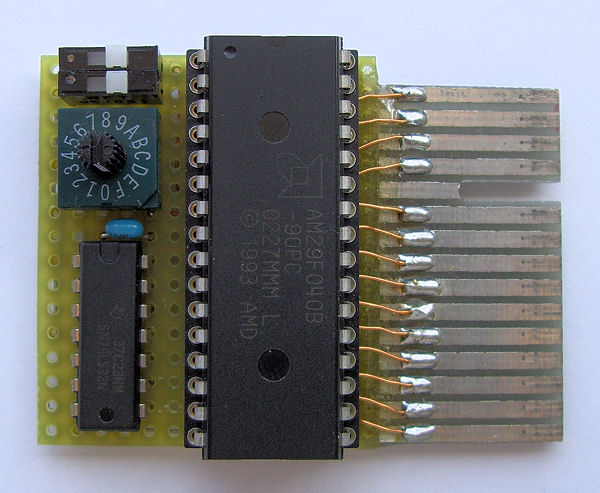 This picture shows the finished module with the ROM plugged in. To the left of the ROM you can see IC2 and above it the bank selection switches. Unfortunately the dip switches were only available in
a double pack, so one of them remains unused.
This picture shows the finished module with the ROM plugged in. To the left of the ROM you can see IC2 and above it the bank selection switches. Unfortunately the dip switches were only available in
a double pack, so one of them remains unused.
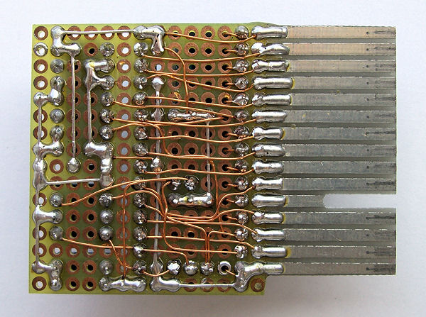 Here you can see the conductor side of the circuit board. 0.3 mm enamelled copper wire was used for the wiring. It takes a bit of getting used to, but with a little practice you can manage it.
The Flash ROM now needs to be filled with data before the module can be used. In addition to the data file, a programming device is required. On my electronics pages I present an EPROM programmer that can also program the 29F040B used here.
The contents of the individual memory banks can be combined as required. To do this, you must first obtain the required ROM files. In addition to the 10 original games, you can find other ROMs, such as emulators for the ZX80 and ZX81, or test ROMs, on the aforementioned site www.fruitcake.plus.com. If you have the desired ROMs in binary format with a length of 16384 bytes, you can copy them together into an EPROM file in the following way:
- Open the Windows command prompt
- Change to the drive where the ROM files are stored, e.g.: d:
- Change to the directory where the ROM files are located, e.g.: cd \spectrum\roms
- For example, the ROMs rom1.bin, rom2.bin, rom8.bin and rom7.bin should be used.
- Enter: copy /b rom1.bin + rom2.bin + rom8.bin + rom7.bin eprom.bin
- The generated eprom.bin file must now be programmed into the Flash ROM.
I had already prepared something:
| Bank 0 | Space Raiders |
| Bank 1 | Masterchess |
| Bank 2 | Planetoids |
| Bank 3 | Hungry Horace |
| Bank 4 | Backgammon |
| Bank 5 | Horace & The Spider |
| Bank 6 | Jet Pac |
| Bank 7 | Pssst |
| Bank 8 | Tranz Am |
| Bank 9 | Cookie |
| Bank A | ZX81 Emulator (for Spectrum 128k) |
| Bank B | Sinclair System Test ROM Cartridge |
| Bank C | Spectrum 128 RAM Tester |
| Bank D | HDT-ROM (Read more) |
| Bank E | ISO-ROM (Read more) |
| Bank F | ZX Spectrum ROM (normal 48k ROM) |
Only 16 of the 32 available banks are used in this ROM file. Unfortunately, it contains ROM files that may not be copied. For this reason I have removed the original download link.
The ZX Spectrum 128k and its successor models +2, +2A, +2B and +3 have a connector for an RS-232 interface. This allows communication with other serial devices such as computers, modems or printers. This interface can also be used for MIDI data, but only in one direction: it is only possible to send data (MIDI Out). Unfortunately, Sinclair (and later Amstrad) used the rather impractical connectors labelled BT 631W (right-handed). These are almost impossible to find, especially in Germany. Only the similar BT 631A can be bought relatively cheaply, e.g. on Ebay. With a bit of skill, you can modify these plugs to fit the Spectrum's jacks. The best thing to do is to order a complete cable, so that you can save yourself the trouble of crimping and have 2 plugs at your disposal. Make sure you order the 6 pin cable version.
 I used a ready-made 3 metre cable with a BT 631A plug at each end. This was then cut off in the middle. The picture on the left shows such a plug with cable in the original
and on the right the same plug after processing. One of the edges has been removed with a fine rasp, and the plug now fits almost perfectly into the Spectrum 128k's socket, which was originally
intended for the BT 631W. The result may not look pretty, but it works fine.
I used a ready-made 3 metre cable with a BT 631A plug at each end. This was then cut off in the middle. The picture on the left shows such a plug with cable in the original
and on the right the same plug after processing. One of the edges has been removed with a fine rasp, and the plug now fits almost perfectly into the Spectrum 128k's socket, which was originally
intended for the BT 631W. The result may not look pretty, but it works fine.
 A complete MIDI cable requires a 5-pin DIN connector (180°). This is soldered to the end of the cable as shown in the diagram opposite. Alternatively, you can use a 5-pin socket or coupling, but then
you will also need a MIDI patch cable. Whatever you choose, the 1kΩ resistor R1 is important. The MIDI standard specifies a current loop of 5 mA, and given the output level of 12V and the internal
resistor of 1kΩ in the CTS line, this is a good fit.
A complete MIDI cable requires a 5-pin DIN connector (180°). This is soldered to the end of the cable as shown in the diagram opposite. Alternatively, you can use a 5-pin socket or coupling, but then
you will also need a MIDI patch cable. Whatever you choose, the 1kΩ resistor R1 is important. The MIDI standard specifies a current loop of 5 mA, and given the output level of 12V and the internal
resistor of 1kΩ in the CTS line, this is a good fit.
The MIDI interface of the ZX Spectrum 128k can also be used in 128k BASIC. There is an additional PLAY command which allows you to play sounds and noises in 3 voices using the internal AY sound chip. With the appropriate programming, the note values can also be output via MIDI, even with up to 8 voices simultaneously. This requires a suitable MIDI instrument to be connected, e.g. a General MIDI synthesizer. If such an instrument is not available, an inexpensive device based on the IC SAM2695 will suffice:
- GM mini module
- GuMP - General midi player
- MIDI Synthesizer Unit von M5Stack (still needs an optocoupler and some components for MIDI In)
As mentioned above, you can use the MIDI interface in 128k BASIC. The PLAY command is well described in the ZX Spectrum 128k manual, but the MIDI function is not so well explained. So here is some additional information:
- To enable MIDI output, insert the command Y followed by a number between 1 and 16 into the note string. This number determines the MIDI channel for which the following notes are intended. Ideally, the Y command should be placed at the beginning of the string. However, it can be used anywhere, e.g. to change the MIDI channel.
- A total of 8 strings can be defined in order to play 8 voices simultaneously via MIDI. To do this, the MIDI channel must be defined in each string using the Y command. The channel numbers can be any number between 1 and 16. For example, you can use the same MIDI channel for chords in 3 strings. Other strings then use different MIDI channels for bass, melody and drums.
- When MIDI output is enabled, all notes are sent to connected instruments via the Note On and Note Off MIDI commands. The volume set with the string command V is also taken into account. This volume value (0-15) is multiplied by 8 and then output as the velocity byte in the Note On MIDI command. The volume has no effect on the Note Off MIDI command; here the value 64 is always output as the release byte.
- A further string command Z is available to output any bytes via MIDI. The Z must be followed by a number between 0 and 255, and this number is then output as a byte via MIDI. You have complete freedom here, as any MIDI command can be generated, e.g. program change, controller change, pitch bend or even system exclusive. However, you should be familiar with the MIDI data structure, as nonsensical or incorrect MIDI commands will not cause any damage, but will not produce the desired result.
- Important: The Z string command only works if the MIDI output has previously been activated with the Y string command. However, the MIDI channel set with Y only applies to the notes in the string and not to the Z command. The MIDI channel must be taken into account when determining the value.
The package zx128-midi.zip contains 3 examples to test the MIDI function. Unfortunately some of the current memory solutions like DivIDE or DivMMC do not work in 128k BASIC. For this reason I have created each example in 3 variants (BAS, TAP, SNA) and you have to try which one works. The 3 examples do the following:
| midi1 | Plays a small demo song using only the AY sound chip. There is no MIDI output yet. |
| midi2 | Plays the same song via MIDI. You should hear a clear difference compared to the AY sound from midi1. |
| Crockett | Plays the song Crockett's Theme (Jan Hammer) in 8 voices via MIDI. |
Even more MIDI is possible with the ZX MIDI Player. Have fun with it.
Compared to its predecessors, the ZX Spectrum Next is equipped with a relatively large number of interfaces, although you won't find any MIDI connectors. However, the Next's hardware has many features that allow you to add a full MIDI interface with relatively little effort. This also includes 2 UART units (Universal Asynchronous Receiver Transmitter), which are responsible for communication with the WiFi module (ESP8266) and the accelerator board (Raspberry Pi) during normal operation. The UART lines RX and TX can be redirected to the joystick ports via a special Next register and are directly available there. Important to know: The modified UART can no longer control the original device (WiFi or accelerator). This is not a problem - a reset of the ZX Spectrum Next will restore the original state.

The MIDI interface is serial and transmits information via a pair of wires at a rate of 31250 baud. The transmitter (MIDI OUT) forms a current source that controls the LED of an optocoupler in the receiver (MIDI IN). The received data is available at the output of the optocoupler and can be analysed and also forwarded to other devices via another current source (MIDI THRU).
The adjacent picture shows the schematic for the Next MIDI Box, which largely follows the recommendations of the MIDI Association. The transmit signal from joystick connector pin 7 (UART TX) is first passed through 2 logic inverters and then to socket X2 (MIDI OUT). The inverters IC1.4 and IC1.5 are not only used as drivers for the MIDI output, but also to adjust the level of the TX signal from the Spectrum Next, which operates at 3.3V. Another inverter, IC1.6, is used to drive the LED D1, which is used to indicate data transmission to MIDI OUT.
On the receiver side, the signal is routed from socket X3 (MIDI IN) to the LED of optocoupler IC2. The received signal is then tapped at the output of the phototransistor (pin 6) and routed to
joystick connector pin 9 (UART RX). At the same time, this signal is routed via logic inverters IC1.1 and IC1.2 to socket X4 (MIDI THRU), allowing the received data to be output to other devices.
Again, another inverter IC1.3 serves as a driver for LED D3 to indicate the data received at MIDI IN.

If you only want to use the Next as a MIDI file player, you can omit the entire circuit section for receiving MIDI data. This leaves IC1, D1, R1, R2, R3, C1, C2, X1 and X2. This circuit fits into a
very small case.
Both diagrams can also be downloaded as PDF files: next-midi-box.pdf.
| Quantity | Part | Number | Remark |
|---|---|---|---|
| 1 | IC 74LS04 | IC1 | DIP version |
| 1 | IC 6N137 | IC2 | DIP version |
| 1 | LED Red | D1 | any type |
| 1 | LED Green | D3 | any type |
| 1 | Diode 1N4148 | D2 | |
| 5 | Resistor 220Ω | R1, R2, R4, R6, R7 | metal |
| 2 | Resistor 1kΩ | R3, R8 | metal, adapt to LED D1 und D3 |
| 1 | Resistor 4.7kΩ | R5 | metal |
| 2 | Capacitor 100nF | C2, C3 | ceramic |
| 1 | Capacitor 10µF/16V | C1 | electrolytic radial |
| 1 | D-Sub 9-pin female connector | X1 | |
| 3 | DIN 5-pin female connector | X2-X4 | 180°, printed version |
A note on the D-sub connector: The joystick sockets on the ZX Spectrum Next are designed to accept only a flat D-Sub connector. The connectors with a standard housing will not fit, and there must be
no locking screws. I used a socket with insulation displacement connector and a ribbon cable. Alternatively, you can use a ready-made joystick cable with plug, which you can order as a spare part
from Sintech, for example.
 The whole circuit was built on a breadboard. The 3 large DIN sockets at the bottom are easy to see. I placed the two LEDs to the left and right of them. I was a bit wasteful here and used 5mm RGB
LEDs. Only the red colour (MIDI OUT) was used for the left LED and the green colour (MIDI IN) for the right LED. You can use any LEDs you like or just leave them out.
The whole circuit was built on a breadboard. The 3 large DIN sockets at the bottom are easy to see. I placed the two LEDs to the left and right of them. I was a bit wasteful here and used 5mm RGB
LEDs. Only the red colour (MIDI OUT) was used for the left LED and the green colour (MIDI IN) for the right LED. You can use any LEDs you like or just leave them out.
To connect to the ZX Spectrum Next, I used a 10 pin box connector on the left side of the board. This is where the socket connector will be plugged in later, using insulation displacement technology
with a ribbon cable. If you decide to use a pre-assembled joystick cable, you do not need these connectors. In this case you can solder the cable wires directly to the board.
 This picture shows the board from below. Most of the connections were made with tinned copper wire (0.6mm). For the rest I used enamelled copper wire (0.3mm).
 In this picture the PCB is mounted in the lower part of the case. I used a plastic case (123mm x 70mm x 30mm), which consists of 2 half-shells that can be easily plugged together. There are also 4
domes to support and fix the board. You have to organise suitable screws yourself.
In this picture the PCB is mounted in the lower part of the case. I used a plastic case (123mm x 70mm x 30mm), which consists of 2 half-shells that can be easily plugged together. There are also 4
domes to support and fix the board. You have to organise suitable screws yourself.
For the DIN sockets, the LEDs and the cable, suitable cut-outs must be sawn or drilled. For the LEDs and cable, it is sufficient to cut out the bottom half of the case; for the DIN sockets, the top
half must also be cut out.
 Here you can see the complete Next MIDI Box with the connection cable. A smaller case would have been possible here, but it was not available at the time.
As mentioned above, the joystick connector socket cannot be fitted in a case. However, the insulation displacement connector used here is easy to handle even without a case.
Another note: If one of the following MIDI programs is started on the ZX Spectrum Next, then the MIDI function is active on joystick port 2 and the Next MIDI Box should also be connected there. However, there is a peculiarity: the Next always outputs serial data on both joystick ports, but reading serial data only works on the active port. In practice this means that the Next MIDI Box can be used on both joystick ports if data is only sent via MIDI OUT. Receiving via MIDI IN will only work on joystick port 2.
At the moment there are 2 applications available for the Next MIDI Box:
- Simple MIDI Monitor - This program was written in NextBASIC. It demonstrates the reception of data via MIDI IN, evaluates the data and displays it in form of a list.
- ZX MIDI Player - This player can play standard MIDI files on the ZX Spectrum 128 and also on the ZX Spectrum Next via this box. See the page Software for more information.
 For those who want to experiment with MIDI on the Next, I have made the package midiuart.zip available for download. It contains all the important elements for
MIDI communication and 2 examples in NextBASIC. The part of the program shown in the picture is responsible for initialising the MIDI function.
For those who want to experiment with MIDI on the Next, I have made the package midiuart.zip available for download. It contains all the important elements for
MIDI communication and 2 examples in NextBASIC. The part of the program shown in the picture is responsible for initialising the MIDI function.
Line 9010 sets joystick port 2 (Joy 2) to I/O mode and redirects the WiFi module's UART (UART0) to this port. The next line causes further communication with UART0 (UART0 and UART1 use common I/O ports). It also sets the 3 most significant bits (16, 15 and 14) for the prescaler, which are always 0 at the MIDI baud rate of 31250. Line 9030 resets the UART function and clears the transmit and receive buffers. The next line sets transmission to 8N1 (1 start bit, 8 data bits, 1 stop bit; no parity).
There is another peculiarity when setting the baud rate. The clock for the UART is derived from the clock of the video signal and this can be between 27 MHz and 33 MHz. The first step is to read the
current video mode and determine the associated clock frequency. This is done from line 9050 and the value for the UART prescaler can be calculated in line
9140. This must now be converted into 2 7-bit values, which is done in lines 9150 and 9160. The two 7-bit values are then sent
one by one to the appropriate port in lines 9170 and 9180. Before doing this, it is necessary to mark the more significant 7-bit value by setting bit
7.
 This picture shows 3 subroutines responsible for MIDI communication. The subroutine in lines 9200-9220 can be used to determine whether the UART receive buffer contains data.
To do this, the variable %x is evaluated after the subroutine is called. A value of 0 means that the buffer is empty and a value of
1 means that at least one byte has been received via MIDI In and must be retrieved.
This picture shows 3 subroutines responsible for MIDI communication. The subroutine in lines 9200-9220 can be used to determine whether the UART receive buffer contains data.
To do this, the variable %x is evaluated after the subroutine is called. A value of 0 means that the buffer is empty and a value of
1 means that at least one byte has been received via MIDI In and must be retrieved.
The subroutine in lines 9230-9250 reads a byte from the UART receive buffer and transfers it to the %r variable. Of course, this only makes sense if the UART receive buffer has been checked before and data is available. Otherwise it will return 0, which is no different from a real received 0.
The last subroutine in lines 9270-9300 is responsible for sending a byte via MIDI Out. The byte to be sent must be stored in the variable
%t before the call. Before sending to the UART, line 9280 checks if there is space in the UART send buffer and waits if necessary.
 This picture shows 2 examples of MIDI data transmission. The program from line 100 demonstrates receiving data via MIDI In. When the program is started
with GOTO 100, the UART is first initialised for the MIDI function. Line 120 then checks if the UART receive buffer contains data. If there is no data,
the system returns to the check and the program is executed in a loop. Otherwise, line 140 fetches a byte from the buffer. The following line displays this byte on the screen
and the loop starts again.
This picture shows 2 examples of MIDI data transmission. The program from line 100 demonstrates receiving data via MIDI In. When the program is started
with GOTO 100, the UART is first initialised for the MIDI function. Line 120 then checks if the UART receive buffer contains data. If there is no data,
the system returns to the check and the program is executed in a loop. Otherwise, line 140 fetches a byte from the buffer. The following line displays this byte on the screen
and the loop starts again.
The program from line 200 onwards demonstrates the sending of data via MIDI Out and also starts to initialise the UART. Lines 220-240 send 3 bytes corresponding to the following MIDI command: Note On, channel 1, note C4, velocity 127. Then it waits 200 ms and sends 3 bytes again with the following MIDI command: Note Off, channel 1, note C4, release 64. When starting the program with GOTO 200, a MIDI controller connected to MIDI Out should briefly play the note C4 (middle C).
Note: The examples are for demonstration purposes only and are not designed for high performance. Data may be lost during reception due to a UART buffer overflow.